Choosing the right plate heat exchanger is not just about selecting a model — it’s about matching your system’s heat load, flow rate, and temperature conditions. An incorrectly sized unit can lead to poor performance, higher energy costs, and unnecessary system stress.
In this guide, we’ll walk you through how to properly size a plate heat exchanger, including BTU calculation, plate count selection, heat transfer formulas, LMTD, and flow rate considerations. This will help you choose the most efficient and cost-effective solution for your application.
Why Proper Sizing of a Plate Heat Exchanger Matters
Selecting the correct plate heat exchanger is critical for achieving stable and efficient system performance. Improper sizing is one of the most common causes of inefficiency in real-world heating and cooling systems.
If the unit is undersized:
- Outlet temperature may not reach target levels
- Heat transfer capacity will be insufficient
If the unit is oversized:
- Higher upfront equipment cost
- Increased pumping energy consumption
- Reduced operational efficiency
Other potential issues include:
- Excessive pressure drop
- Uneven flow distribution
- Faster wear of system components
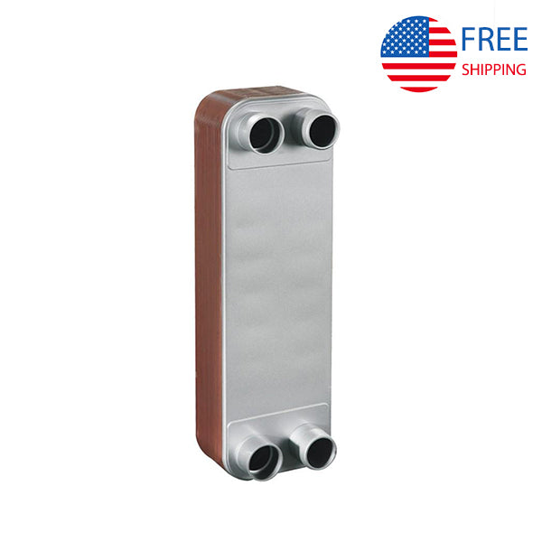
When selecting from our Plate Heat Exchangers, it’s important to evaluate not just the size, but also system conditions such as flow rate, heat load, and temperature difference.
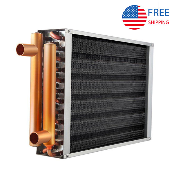
Compared with Shell & Tube Heat Exchangers, plate heat exchangers offer higher efficiency but require more precise sizing to achieve optimal results.
Understanding Heat Load: BTU, kW, and System Requirements
Heat load defines how much thermal energy must be transferred in your system. It is the foundation of all heat exchanger sizing calculations.
Common Units
- BTU/hr (British Thermal Units per hour)
- kW (kilowatts)
Basic Calculation (Water Systems)
- BTU/hr = 500 × GPM × ΔT
- kW = Flow Rate × ΔT × 4.186
Where:
- GPM = flow rate (gallons per minute)
- ΔT = temperature difference
Typical Heat Load by Application
| Application | Typical Heat Load |
|---|---|
| Residential floor heating | 10,000 – 50,000 BTU/hr |
| HVAC systems | 50,000 – 500,000 BTU/hr |
| Industrial cooling | 500,000+ BTU/hr |
For example:
- A home heating system like Floor Heating usually requires a compact unit
- Large systems such as Data Center Cooling System demand significantly higher capacity
Accurately calculating heat load ensures that your brazed plate heat exchanger performs efficiently without being over- or under-sized.
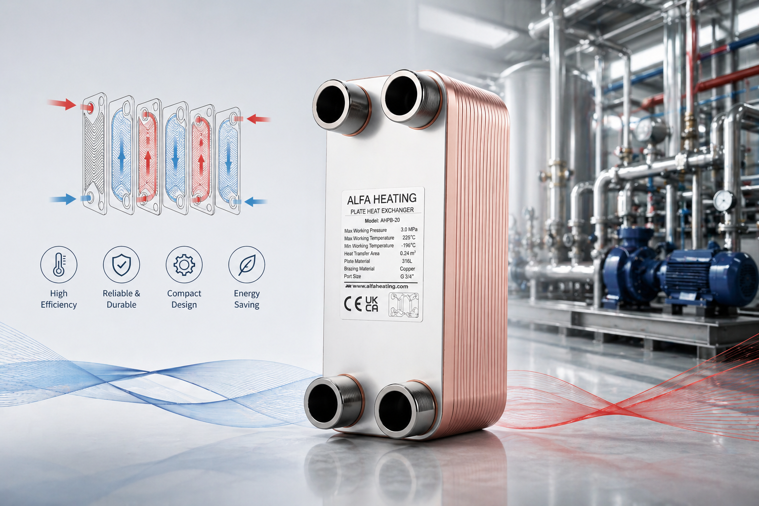
Plate Count vs Heat Transfer Capacity
The number of plates in a heat exchanger directly determines its heat transfer capability. Increasing the plate count expands the total heat transfer surface area, allowing more efficient energy exchange between fluids. However, plate count is not only about increasing capacity — it also has a direct impact on pressure drop and overall flow performance.
Key Relationships
- More plates → larger heat transfer area
- More plates → higher thermal efficiency
- More plates → higher pressure drop
Important Considerations
Selecting the right plate count requires balancing multiple factors:
- Heat transfer performance
- Pressure drop across the system
- Flow distribution efficiency
Adding more plates improves heat transfer, but excessive plate count can increase resistance and pumping energy consumption. The goal is to find the optimal balance between efficiency and system load.
A common mistake is selecting a unit based only on connection size, rather than actual heat load and flow requirements. This often leads to either underperformance or unnecessary energy use.
For applications such as HVAC Systems, choosing the correct plate count is essential to maintain stable temperature control and overall system efficiency.
Heat Transfer Calculation and LMTD Explained Simply
Basic Heat Transfer Formula
Where:
- Q = heat transfer rate
- U = overall heat transfer coefficient
- A = heat transfer area
- ΔT = temperature difference
Increasing the number of plates increases surface area (A), which improves heat transfer performance.
What Affects the Heat Transfer Coefficient (U)?
- Fluid properties (water, oil, refrigerant)
- Flow turbulence
- Fouling or scaling
- Plate design and material
The corrugated plate design creates turbulence, significantly improving heat transfer efficiency compared to traditional designs.
What Is LMTD (Log Mean Temperature Difference)?
LMTD (Log Mean Temperature Difference) represents the effective temperature difference between hot and cold fluids across a heat exchanger. Since temperatures change along the flow path, LMTD provides a more accurate value than a simple average.
- Higher LMTD → better heat transfer efficiency
- Lower LMTD → reduced performance
Flow Type Comparison
- Counterflow (recommended): higher LMTD and better efficiency
- Parallel flow: lower LMTD and less efficient
In most applications such as HVAC Systems, counterflow design is preferred for optimal performance.
Flow Rate vs Heat Load: How to Match Your System
Flow rate directly impacts how effectively heat is transferred.
Key Relationships
- Higher flow rate → increased heat transfer
- Excessive flow → higher pressure drop
- Low flow → reduced efficiency
Recommended Flow Velocity
- Typical range: 0.5 – 2.5 m/s
Balancing Efficiency and Pressure Drop
There is always a trade-off between heat transfer efficiency and pressure loss. Optimizing both is key to proper system design.
Application Examples
- HVAC systems → high flow, low temperature difference
- Oil cooling systems like Industrial Oil Cooling → lower flow, higher temperature difference
Matching flow rate with heat load ensures consistent system performance and avoids unnecessary energy consumption.
How to Choose the Right Plate Heat Exchanger (Quick Selection Guide)
Follow these steps to select the right unit:
Step 1: Calculate Heat Load
Determine required BTU/hr or kW
Step 2: Confirm Flow Rate
Understand system flow requirements
Step 3: Define Temperature Conditions
Identify inlet and outlet temperatures
Step 4: Select Plate Count
Match capacity with plate number
Selection Checklist
Before choosing a unit, confirm:
- Fluid type (water, oil, refrigerant)
- Flow rate
- Temperature range
- Pressure limits
- Installation environment
For example:
- Residential systems require compact and efficient units
- Industrial & Heavy-duty applications demand higher durability and capacity
Pro Tip
Applications such as Marine & Offshore require careful material selection and corrosion resistance in addition to proper sizing.
Common Sizing Mistakes to Avoid
Avoid these common errors when selecting a heat exchanger:
- Ignoring flow rate requirements
- Oversizing “for safety” (leads to inefficiency)
- Not considering pressure drop
- Choosing incorrect materials
- Neglecting maintenance requirements
Correct sizing is about balance — not simply choosing the largest unit available.
A properly sized plate heat exchanger ensures optimal performance, energy efficiency, and long-term reliability. By understanding heat load, plate count, flow rate, and LMTD, you can make a well-informed decision.
If you're unsure how to size your unit, our engineering team can help. Simply provide your system parameters, and we will recommend the most suitable solution for your application.

![Brass Barbed Tees 1/2"x1/2"x1/2" Lead Free PEX Crimp"T" Fitting [5pk, 10pk, 25pk]](http://alfaheating.com/cdn/shop/products/brass-barded-tee.jpg?v=1603079042&width=600)